I’m stunned and looking for suggestions for my 2023 Vilano 393GS
As some of you may remember, I’ve had issues with room temperature control and finally discovered the issue. My room temperature sensors are not where they should be, nor are they correctly wired.
1 - The master bedroom sensor is wired as the middle room.
2 - Mid room sensor is wired as the master bedroom.
3 - The read bedroom sensor is physically located above the control panel vice in the rear room.
To be honest, I wasn’t sure what these little sensors were until I accidentally held my hand over one of them and noticed the indicated temperature change. The lights in my head came on…this is why I’ve been having issues maintaining the room temps.
So, my question is how do I change identify which wire is which at the additional Spyder center for room temperature control? and how do I best run new wire and change the location of the rear bedroom sensor? I think I need a deep dive into the temperature control system in the rig.
I do recall your issue. You are correct in that you identified those temperature sensors around the rig. As you have found placing your hand over the sensor is a good way to identify how they are currently wired. Having the wires crossed on the thermistors was a common issue in units manufactured in 2022 / 23 - I was told they had the wiring bundle created incorrectly for a period of time for some units.
The wires for those temperature sensors all run back to the RS-9 board that is connected to your Spyder system. If I recall correctly you found and posted a picture of your RSI-9 board. It is relatively easy to correct once you have located that board. You can buy a de-pinning tool from amazon that will remove the wires from the plug where those sensor wires feed into and swap them to their correct location within that plug. Some people will cut and splice the wires that go into the connector to swap them around and of course that works too but I would lean toward de-pinning.
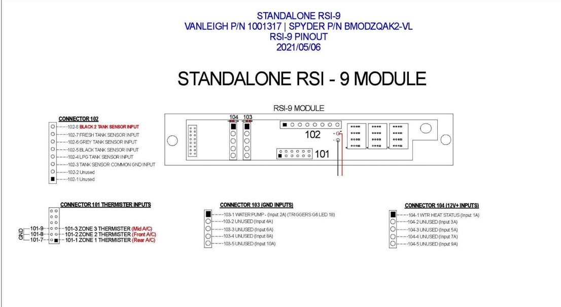
I am going to place the pinout for the RSI-9 board below with the temp sensors for each unit labeled so you can reference where those wires connect into the 101 connector on that board.
Spyder Controls has excellent customer service and have walked many people through this swap if you need. They can be reached at 1-866-919-9092.
If it is a 2023 model year you probably have the G12 models which do not use the RSI9. On the VL owners Facebook group there are diagrams in the file section of the G12. You need to move the sensor wires at the module.
Eric - I was puzzled by this as well but Chris posted his RSI-9 board in a previous post. That unit must have been in the early 2022 year where they were still making the transition to the G12. The 393GS was only manufactured for the 23 model year so is odd that it has a RSI-9.
Many of the folks in this group dont use Facebok so the pinouts for both the G12s and G6 are located at this link:
I am also experimenting with a “FILES” section that should be in the left side of the menu. Discourse isnt that friendly with a location for files so this is currently a link to one of my Google Drives.
First it was a positive for me to see you still engaged with us. Been praying for y’all.
I did not know he showed the RSI9, meaning he has G6.
Thanks as always for taking care of us.
Question for you, how many AC units do you have on the roof? How many AC units show up on your control panel? Are you only concerned about the cooling?
Someone correct me if I am wrong, but it’s my understanding there is only one common vent path for all AC units, so each AC unit just adds more air to the common path. Each sensor should only control 1 AC unit. There is a little more air flow where the AC units are located and it depends if the fans are on high or low.
Does that rear sensor kick on any of the AC units? Hopefully the rear AC.
Hi Lynn and thank you for the reply and questions.
My rig has three AC units and I believe it is not a common header.
The master bedroom has a combo AC/Heat Pump unit for controlling the temps in the forward compartment. The furnace is also controlled, via the control panel, but associated with the master bedroom/forward compartment.
The main living area has its own AC unit, controlled from the master controller. The heat comes from the furnace or the fireplace which has its own controls.
The 2nd bedroom has a third AC unit, again, controlled at the main control panel. The only heat in that room comes via the furnace.
You all are amazing. I’ll get to work identifying which wire is associated with the sensors. I did reconnect a couple following my previous post but learning which sensor is which answers some of the questions from earlier.
Now I just need to find out the best way to relocate the rear sensor and run the wires. I prefer to not pull the ceiling panels down. Ugh…
Lynn your thinking is correct. The street side is the return and curb side is the supply and all share that common path. We boondock / drycamp alot and we wanted to run one AC off our battery bank for the bedroom. We blocked the path to the rest of the ducts separating the bedroom so as not to share with the rest of the rig.
The issue that Chris is describing was a semi common issue in 2022 where the wiring for the thermistors were swapped at the control board.
Chris just verifying, when you are in your front bedroom and you place your hand over the sensor you see the temperature for the mid AC rise vs the front AC?
Chris during one of my stays at the Tiffin Service Center in Redbay I ran into a tech that would change the physical sensor location (seemed to be a common complaint). Vanleigh standardly placed one sensor in the front bedroom and no matter what model you have they placed the mid and rear next to the Spyder panel. This wasnt a huge issue for me as my model 34RLB / 320 the mid and rear shared one large space although I would have preferred my physical sensor to be in the rear. You would think in your model with that rear bedroom they would have put the physical sensor in that room.
That tech in Redbay gave me an extra sensor that I was going to mount it to the rear wall of my unit and run the wires down following the same path as some of my electrical that went back to the Spyder control through the underbelly. I dont know that I would pull down the ceiling panels. If you decide to take on the task of relocating that rear sensor let us know how you decide to run it. I was going to leave the old sensor next to the Spyder panel just to avoid having to repair the holes. It might pay to buy another to run to that back room. This is the one I was buying before it was given to me.